 |
|---|
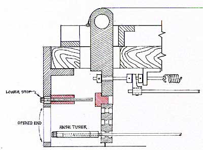
The major modifications are seen in red (diagram at right).
* The lowering stops were removed, and the casting cut back for better access to the string end.
The casting behind the changer is cut back. * The entire raise stop mechanism and cross plate was removed.
* A fill block was pressed and epoxied into the hole where the raise stop came through the changer finger.
* The holes through which the raise stops ran were opened up to allow clearance for a 6-32 socket head cap screw.
* A bar was attached from the inside to the end plate. This bar was tapped for 12 6/32 socket head cap screws to screw through. These were the lower stops. The screws were stiffened by the use of Loc-Tite.
* The end of the end plate was milled open to allow passage of the raise tuners.
The end casting was opened for access to the new bellcrank rod adjustments.
* The raise rods were threaded to a 6-32 thread (a very loose fit since a 6-32 thread should be cut on an .138 rod and not a .125) and then a piece of heat shrink tubing was applied to the threads.
* The raise tuner itself was a long collar, threaded for 6-32. In one end a 6-32 socket head cap screw was inserted and Loc-tited into place. The whole assembly was screwed onto the rod. Since the 1/8" rod was a bit smaller than the outside diameter of a 6-32 screw, the heat shrink tubing allowed the thread in the collar to cut into the tubing, giving a solid fit, that is still adjustable.
The re-done underside. The two bellcranks seen are the RKR which lowers my 2nd and 9th string. The lower yokes that straddle and push on the lower rods are seen underneath, just to the left of the return springs. The words "the steel, number 2" are cut into the machine-turned aluminum plate on the front apron that holds the cross-rods.
Of course, I re-did all the bellcranks and the mountings of the cross-rods using the idea of split pillow blocks. The bellcranks were made to cinch tight around the stainless cross-rods.
 |
|---|
There are no reversing cranks used. The left moving knee-levers had the pulls above and the lowers (push) below. The right moving knee-lever are all lowers, so the bell crank is above the axle (as seen in the photo of the changer above).
I also stiffened the body with 4 pieces of carbon-fiber rod. These were used by Ovation to keep the guitar neck from warping. The pieces were about 24" long, half-inch wide, and 3/32nd thick. I inset two into the body under the neck, and one each into the bottom edge of the front and rear apron. You can see the black stripe on the rear apron of the guitar in its case. The piece on the front apron goes from edge to edge-- the reason the bottom edge of the front apron is black.
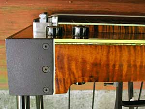
When I cut the end off, I lost the "re-curve" on the rear apron. I removed the section from the cut piece, and spliced in onto the rear apron. A careful look will show the line where this was done. Of course, the wood on the added piece did not have a matching figure. That was solved by airbrushing in a few stripes that carried over from the rear apron, and then adding a final coat of lacquer to the whole rear. From a short distance, the modification is invisible!